Details are critical when it comes to foundry mold design. Whether the casting solidifies incorrectly, a misplaced or missing riser causes a defect, or the mold cools too quickly and cracks, what may seem like a small design change can have big repercussions on the accuracy of a mold and its casting.
Here are just a handful of best practices Anderson Global’s team of design engineers use to ensure you get a permanent mold that makes great parts from the first pour.
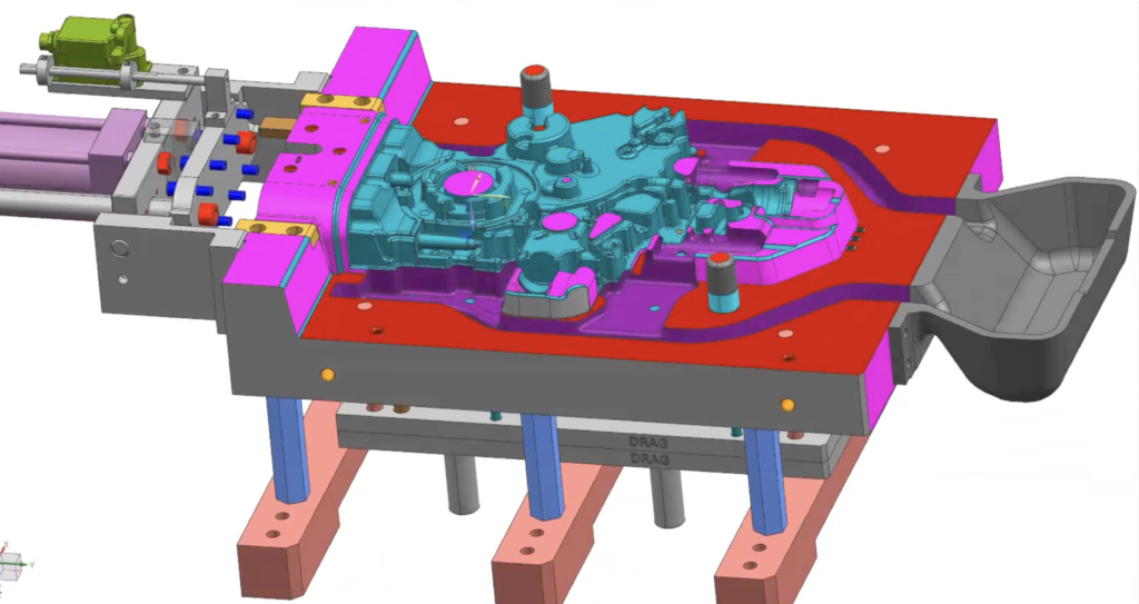
Keys and interlocks leave room for thermal expansion
When it comes to tooling alignment, it’s critical that both halves of the tool align correctly. Using interlocks and keys instead of pins and bushings is a great way to do this. And although this type of locating works well on many types of tooling, it works especially well in processes with a lot of heat, like permanent molds.
The positioning of the keys and interlocks on three sides of the mold allow for centered, even heat expansion across the mold while also maintaining the critical mold alignment.
In contrast, pins and bushings have a greater center-to-center distance between locating pins. In hot molds, this type of uneven heat expansion lends itself to potential binding issues. This, in turn, wears out the locating components much faster and results in inaccurately aligned mold.
While we prefer to design our molds with keys and interlocks, we can still use pins and bushings depending on customer preference. And many customers still prefer pins and bushings because that is the traditional design technique for mold locating. In those cases, our team takes special care to avoid binding issues by ensuring the proper clearances and best practices are used.
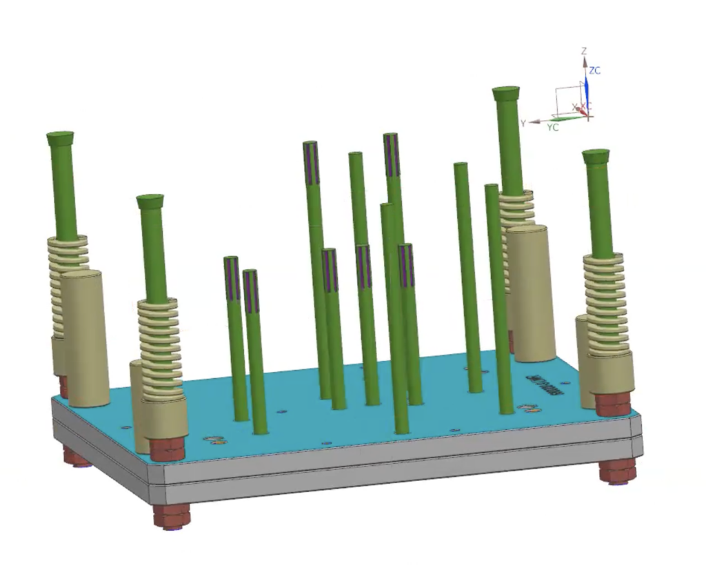
Hex posts improve manufacturing efficiency
Mold standoff posts are a simple, yet critical feature of permanent molds. They ensure there is enough range, distance and height built into the design to allow room for ejector systems and cooling components. They also guarantee that the tool will reach the minimum height requirements to fit within the given molding machine.
Hex posts and round posts are two common types of mold standoffs. Both options work well, but using hex posts over round posts eliminates manufacturing steps.
With round posts, their circular shape makes them difficult to grasp and tighten. This means you’ll either need to machine flats to the post or grab a big pipe wrench and use some elbow grease. But with hex posts, machinists simply have to cut the posts to the correct length, drill and tap holes, and then the post is ready for use.
Work holding capabilities ensure consistency
While our customers don’t see this best practice firsthand, they feel the benefits of our FCS clamping system, which allows for faster and more consistent work holding throughout our shop.
Instead of spending hours setting up a project on a machine — then hours setting up that same project on the next machine — our machinists can leave the same clamps on throughout the whole process.
Set ups that used to take two or three hours instead happen in 15 minutes. And the time saved by sensible work holding translates directly to cost savings for the foundry.
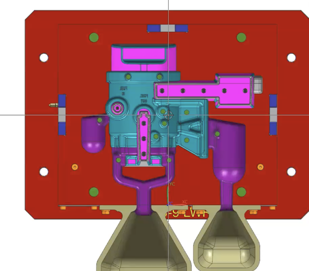
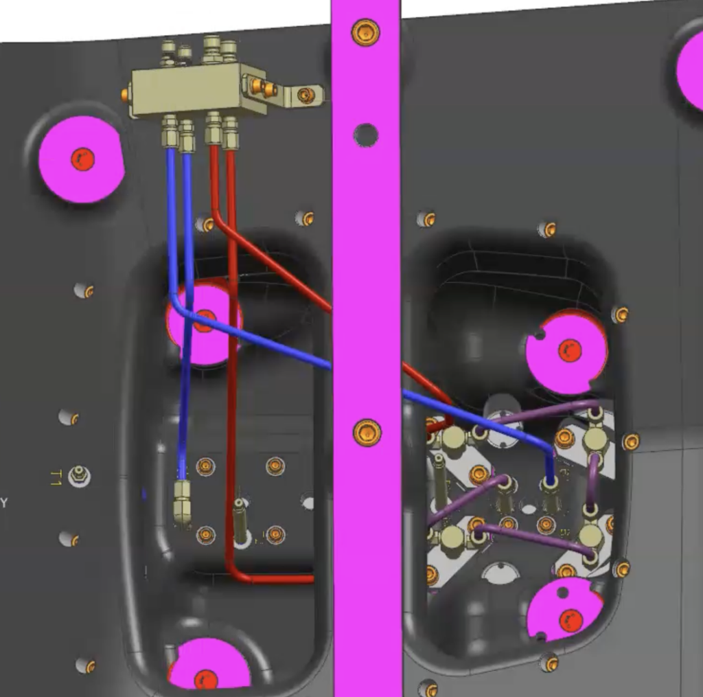
Color-coded designs allow for better communication
By implementing a shop-wide color-coding system, all our 3D models “talk,” meaning they deliver the manufacturing intent across all departments. This allows our programmers and engineers to understand a design’s important features, challenges, and tolerances with just a glance.
For example, a magenta section is going to have a tighter tolerance than a gray section, while English-threaded holes are orange and metric-threaded holes are yellow. When everyone understands and follows the effective color-coding system, it means our tools are more likely to come out correct the first time, every time.
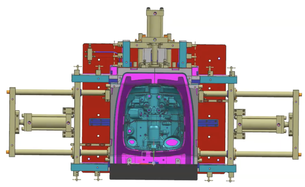
Choosing the right ejector plate system
For optimal mold functionality, use one of two ejector plate system pins: headed pins (like those made by DME) and threaded pins (like the ones made by Baker).
DME pins are more precise and can have a flat machined on to prevent rotation. They’re also readily available, more rigid than Baker pins, and generally more durable. But because the pin heads are sandwiched between two plates, they are not adjustable. This means to change the length of a pin, machinists would have to remove it and cut or replace it as necessary, taking the mold offline while maintenance happens.
Baker pins, on the other hand, are threaded, meaning each individual pin can be adjusted to create the exact desired effect on the tool. This enables foundries to adjust the height of a whole plate, or even just one pin if, for example, heat expansion shifts or pushes the pin.
While each type of pin serves a similar purpose, which one we include in a design ultimately comes down to our understanding of your needs.
Choosing the right cooling strategy: air versus water
Two typical mold cooling strategies are either air cooling or water cooling. Which one we use depends heavily on the foundry’s capabilities and what the mold needs. Some molds don’t require any additional cooling methods. Some require a handful of bubblers. And other may require a complex system of circuits and chill inserts.
Once our design engineers understand a foundry’s needs and requirements, they start with simpler cooling strategies, then move to progressively more complex ones until those requirements are met.
Generally, we prefer to use water cooling over air because water is more effective and efficient. But water cooling isn’t feasible on every project. Beyond safety concerns, foundries need dedicated plumbing hook ups and lines to take advantage of this strategy. They also need to use premium grade steels and other materials that will hold up to the rapid heating and cooling generated from the casting process.
Air cooling, on the other hand, is very accessible. And different techniques and designs – such as turbulent air, fins, and cooling channels – can help speed up the cooling process.
You don’t need to worry about the airflow principles or thermodynamics involved in each individual cooling method. That’s why we’re here. Armed with technical knowledge like this and years of experience, our design engineers have the tools to create effective cooling strategies for any mold, no matter the complexity or material.
Experience makes the difference
Our decades of experience and deep expertise across multiple industries means you get the best design practices from every sector. To learn how we can help you build molds that make better castings, get in touch with our team.